


Description
Overview of Voltage and Frequency Control System
- The ASF-442H Frequency and Voltage Stabilization Control Unit is a core device for voltage and frequency control in power system, control of frequency and voltage, and professional frequency and voltage control.
- It is designed to disconnect specified power equipment such as transmission lines or unit transformers when system frequency or voltage drops, thereby ensuring the safe and stable operation of the power grid.
- It is a load shedding controller.Its main functions include under frequency load shedding and under frequency and undervoltage load shedding, covering low-frequency/low-voltage disconnection, high-frequency/low-voltage disconnection, and rapid startup of standby units under low-frequency/low-voltage conditions, as well as low-frequency detection, low-voltage detection, over-frequency detection, over-voltage detection, and reverse power detection.
Features
Protection Functions
| Item | Description |
|---|---|
| Five-stage low-frequency protection | Configurable slip lockout and low-voltage lockout;
Low-frequency derating supports trip output or alarm output |
| Five-stage low-voltage derating | Five-level low voltage derating function |
| Over-frequency protection | Configurable low-voltage lockout;
Over-frequency derating supports trip output or alarm output |
Communication Functions
| Item | Description |
|---|---|
| Communication Modes | RS-485, CAN, Wired Ethernet, Fiber-optic Ethernet (specify when ordering) |
| Data Upload | Transmits real-time measurement data, waveform data, faults, alarm signals, protection settings, configurations and coefficients. Supports remote online modification of protection settings and enabling/disabling of protection functions. |
| Command Reception | Receives commands from upper system: time synchronization, parameter adjustment, data read and write |
Main Functional Specifications
| Item | Specification |
|---|---|
| Protection response time | Average error ≤ 35 ms (including output relay response time) |
| Precision operating range | 0.08 In ~ 20 In |
| Current setting error | ≤ ±2.5% (for current above 1.00 A) |
| Voltage setting error | ≤ ±3% |
| Measurement accuracy | Current & Voltage: Class 0.2
Active Power & Reactive Power: Class 0.5 |
| Remote signal resolution | ≤ 2 ms |
Event Logging, Fault Recording
| Item | Description |
|---|---|
| Event Logging | Records protection trips, device faults, trip types, time and operating parameters |
| Fault Recording | Stores protection action time, action type and RMS values before & after trigger |
| Recording Duration | 2 cycles before fault, 4 cycles after fault |
| Power-off Data Storage | 48 SOE records, 16 fault reports |
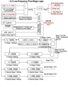
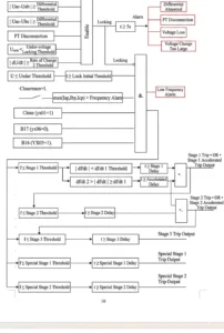
Action Logic Diagram
Setting Table
| No. | Display Name | Range | Step | Remark |
|---|---|---|---|---|
| 1 | Under-frequency Stage 1 Setting | |||
| 1.1 | Under-frequency Stage 1 Enable/Disable | 1/0 | — | Undervoltage protection: Enable(1) / Disable(0) |
| 1.2 | Stage 1 Time Delay | 0~120.00s | 0.01s | |
| 1.3 | Stage 1 Setting Value | 46~50.00Hz | 0.01Hz | |
| 2 | Under-frequency Stage 2 Setting | |||
| 2.1 | Under-frequency Stage 2 Enable/Disable | 1/0 | — | Undervoltage protection: Enable(1) / Disable(0) |
| 2.2 | Stage 2 Time Delay | 0~120.00s | 0.01s | |
| 2.3 | Stage 2 Setting Value | 46~50.00Hz | 0.01Hz | |
| 3 | Under-frequency Stage 3 Setting | |||
| 3.1 | Under-frequency Stage 3 Enable/Disable | 1/0 | — | Undervoltage protection: Enable(1) / Disable(0) |
| 3.2 | Stage 3 Time Delay | 0~120.00s | 0.01s | |
| 3.3 | Stage 3 Setting Value | 46~50.00Hz | 0.01Hz | |
| 4 | Special Under-frequency Stage 1 | |||
| 4.1 | Stage 1 Time Delay | 0~120.00s | 0.01s | |
| 4.2 | Stage 1 Setting Value | 46~50.00Hz | 0.01Hz | |
| 5 | Special Under-frequency Stage 2 | |||
| 5.1 | Stage 2 Time Delay | 0~120.00s | 0.01s | |
| 5.2 | Stage 2 Setting Value | 46~50.00Hz | 0.01Hz | |
| 6 | General Under-frequency Setting | |||
| 6.1 | Startup Time Delay | 0~120.00s | 0.01s | |
| 6.2 | Startup Setting Value | 46~50.00Hz | 0.01Hz | |
| 6.3 | Acceleration Time Delay | 0~120.00s | 0.01s | |
| 6.4 | Df/dt1 | 1.0Hz/s~9.9Hz/s | 0.1Hz/s | Slip blocking setting value |
| 6.5 | Df/dt2 | 1.0Hz/s~9.9Hz/s | 0.1Hz/s | Slip blocking setting value |
| 7 | Over-frequency Protection | |||
| 7.1 | Over-frequency Protection Enable/Disable | 1/0 | — | Over-frequency protection: Enable(1) / Disable(0) |
| 7.2 | Over-frequency Trip Enable/Disable | 1/0 | — | Over-frequency: Trip(1) / Alarm(0) |
| 7.3 | Undervoltage Blocking Over-frequency | 1/0 | — | Undervoltage blocking: Enable(1) / Disable(0) |
| 7.4 | Over-frequency Time Delay | 0.1~120.00s | 0.01s | |
| 7.5 | Over-frequency Setting Value | 50~54Hz | 0.01Hz | |
| 8 | Undervoltage Stage 1 Setting | |||
| 8.1 | Undervoltage Stage 1 Enable/Disable | 1/0 | — | Undervoltage protection: Enable(1) / Disable(0) |
| 8.2 | Stage 1 Time Delay | 0~120.00s | 0.01s | |
| 8.3 | Stage 1 Setting Value | 0~100.00V | 0.01V | |
| 9 | Undervoltage Stage 2 Setting | |||
| 9.1 | Undervoltage Stage 2 Enable/Disable | 1/0 | — | Undervoltage protection: Enable(1) / Disable(0) |
| 9.2 | Stage 2 Time Delay | 0~120.00s | 0.01s | |
| 9.3 | Stage 2 Setting Value | 0~100.00V | 0.01V | |
| 10 | Undervoltage Stage 3 Setting | |||
| 10.1 | Undervoltage Stage 3 Enable/Disable | 1/0 | — | Undervoltage protection: Enable(1) / Disable(0) |
| 10.2 | Stage 3 Time Delay | 0~120.00s | 0.01s | |
| 10.3 | Stage 3 Setting Value | 0~100.00V | 0.01V | |
| 11 | Special Undervoltage Stage 1 Setting | |||
| 11.1 | Special Undervoltage Stage 1 Enable/Disable | 1/0 | — | Undervoltage protection: Enable(1) / Disable(0) |
| 11.2 | Stage 1 Time Delay | 0~120.00s | 0.01s | |
| 11.3 | Stage 1 Setting Value | 0~100.00V | 0.01V | |
| 12 | Special Undervoltage Stage 2 Setting | |||
| 12.1 | Special Undervoltage Stage 2 Enable/Disable | 1/0 | — | Undervoltage protection: Enable(1) / Disable(0) |
| 12.2 | Stage 2 Time Delay | 0~120.00s | 0.01s | |
| 12.3 | Stage 2 Setting Value | 0~100.00V | 0.01V | |
| 13 | General Undervoltage Setting | |||
| 13.1 | Startup Time Delay | 0~120.00s | 0.01s | |
| 13.2 | Startup Setting Value | 0~100.00V | 0.01V | |
| 13.3 | Acceleration Time Delay | 0~120.00s | 0.01s | |
| 13.4 | Voltage Difference Setting Value | 0~100.00V | 0.01V | |
| 13.5 | dv/dt1 | 1.0V/s~9.9V/s | 0.1V/s | Voltage difference blocking setting value |
| 13.6 | dv/dt2 | 1.0V/s~9.9V/s | 0.1V/s | Voltage difference blocking setting value |
| 14 | Overvoltage Protection | |||
| 14.1 | Overvoltage Protection Enable/Disable | 1/0 | — | Overvoltage protection: Enable(1) / Disable(0) |
| 14.2 | Overvoltage Trip | 1/0 | — | Trip(1) / Alarm(0) |
| 14.3 | Overvoltage Time Delay | 0~120.00s | 0.01s | |
| 14.4 | Overvoltage Setting Value | 0~120.00V | 0.01V | |
| 15 | General Setting | |||
| 15.1 | Under-current Blocking Load Shedding | 1/0 | — | |
| 15.2 | PT Disconnection | 1/0 | — | PT disconnection detection: Enable(1) / Disable(0) |
| 15.3 | 3P4W Voltage Wiring | 1/0 | — | 3P4W(1) / 3P3W(0) |
| 15.4 | Measuring Voltage 380V | 1/0 | — | 380V(1) / 100V(0) |
| 15.5 | Current Rated 1A | 1/0 | — | 1A(1) / 5A(0) |
| 15.6 | Blocking Load Shedding Current | 0.5~6A | 0.01A | Secondary rated current |
| 15.7 | Undervoltage Setting Value | 0~100.00V | 0.01V | |
| 15.8 | Undervoltage Blocking Value | 0~100.00V | 0.01V | Undervoltage setting for over-current blocking |
Outline and Installation Dimensions


FAQ
Q1: What is the core function?
A: Shed non-priority loads by stages when grid frequency or voltage drops below setting values to pull grid voltage and frequency back to normal and avoid blackout.
Q2: Does it support multi-stage setting?
A: Yes, multiple independent stages for under-frequency and under-voltage respectively with separate delay and threshold configuration.
Q3: Can it avoid mis-operation?
A: Equipped with blocking logic for short-circuit transient drop, CT/PT failure locking to prevent incorrect load shedding.
Q4: Communication options available?
A: Optional RS485, Ethernet, IEC103 for remote parameter setting and fault record upload.
Q5: Typical application sites?
A: Substations, distributed power stations and industrial power networks for domestic and overseas power projects.
Q:How Under-Voltage Load Shedding Controls Circuit Breakers?
Fault disconnection involves rapidly disconnecting the faulted area from the power grid upon detection of a grid fault or instability to isolate the fault and prevent the impact from spreading;
Emergency frequency and voltage control, on the other hand, involves gradually shedding part of the load or adjusting generation output according to a multi-round strategy when a power deficit causes frequency or voltage deviations, thereby restoring system balance.
The former focuses on fault isolation, while the latter focuses on rebalancing supply and demand.


xiao zhang –
Stable multi-stage shedding logic for system frequency/voltage collapse prevention, flexible parameter setup and standard communication, widely applied in grid substations worldwide.
Jack –
Easy to set, clear logic, and no issues since commissioning.