

Description
Product Usage
- The integrated measurement and control device is primarily used for general measurement and control in the integrated automation systems of substations and power plants; it can also be used independently as a standard measurement and control unit, primarily performing telemetry, telecommand, and telecontrol functions.
Features of Integrated Measurement and Control Device
Device self-test function
- The device automatically detects faults such as RAM, ROM, A/D, and power loss.
- Automatically detect parameters such as setpoints, configurations, and coefficients
Event Log
- Event logs include information on event status and device self-test failures.
Communication Features
- The device supports four communication modes: RS-485, CAN, wired Ethernet, and fiber-optic Ethernet (specify when ordering);
- The device uploads real-time data, including measurement data, digital I/O data, alarm signals, configuration settings, and parameters;
- The device receives control commands from the host system, including remote control and system synchronization.
Monitoring Features
- The device is equipped with telemetry capabilities to measure analog quantities such as current, voltage, active power, reactive power, power factor, and frequency;
- It is equipped with telecontrol capabilities to acquire position signals (such as circuit breaker, energy storage, isolating switch, and remote/local) and other digital signals;
- It is equipped with remote control capabilities to close and open circuit breakers.
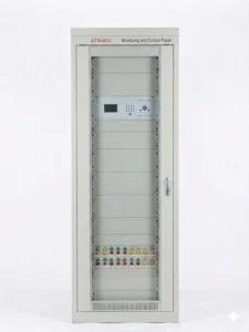
Integrated Measurement and Control Device Panel Assembly & Installation Drawing
The standard features are listed in the table below:
| Board Type | Power Supply Board | Remote Signaling Board | Command Output Board | Analog Board | DC Input Board | DC Output Board | Communication Board |
|---|---|---|---|---|---|---|---|
| Board Configuration | Optional | 32-channel remote signaling | 14-channel remote control | 8U6I | 7/14DC (Optional) | 8AO | 485, CAN, electrical Ethernet and fiber Ethernet communication (Optional) |
General Technical Data
| Category | Item | Specifications | Remarks |
|---|---|---|---|
| Rated DC Specifications | Rated Operating Voltage | 220 V or 110 V | Specific voltage shall be specified when ordering |
| Rated DC Specifications | Ripple Factor of DC Voltage | ≤2% | – |
| Rated DC Specifications | Permissible Range of DC Voltage Fluctuation | 80% to 110% of the rated voltage | – |
| Rated AC Data | Rated AC Current In | 5 A, 1 A | Specific current shall be specified when ordering |
| Rated AC Data | Rated AC Voltage Un | 57.7 V, 100 V | – |
| Rated AC Data | AC Power Supply Waveform Requirement | Sine wave with distortion factor ≤2% | – |
| Rated AC Data | Rated Operating Frequency fn | 50 Hz, with permissible deviation of ±0.5% | – |
| AC Input Range | Continuous Operating Range of Current Input | ≤1.2In | The device can operate continuously when 1.2 times the rated current is applied |
| AC Input Range | Continuous Operating Range of Voltage Input | ≤1.2Un | The device can operate continuously when 1.2 times the rated voltage is applied |
| Power Consumption | Total Power Consumption of the Device | ≤8 W | – |
| Power Consumption | Power Consumption of AC Voltage Circuit | ≤0.5 VA per phase | – |
| Power Consumption | Power Consumption of AC Current Circuit | ≤0.5 VA per phase | – |
Environmental Conditions
Standard atmospheric conditions
Ambient temperature
-
Operating Conditions: Ambient temperature: -20 °C ~ +70 °C; Relative humidity: 5% ~ 95%, no internal condensation or frosting.Storage Conditions: Ambient temperature: -30 °C ~ +80 °C. No irreversible damage shall occur under extreme temperatures without excitation, and the device can resume normal operation after temperature recovers. For packaged units, storage atmosphere pressure: 80–110 kPa (altitude ≤ 2 km), maximum relative humidity: 85%.
Other requirements
- The air around the equipment must not contain any acidic, alkaline, corrosive, or explosive substances.
Surroundings
- The installation site must be protected from sunlight, rain, and snow; shielded against lightning strikes and dust; and well-ventilated;
- Electromagnetic interference exceeding the limits specified in Clause 2.7 is not permitted;
- The installation site shall comply with the Class B safety requirements specified in GB/T 9361;
- The operating environment for the Integrated Measurement and Control Device shall not have vibration exceeding Severity Level 1 specified in GB/T 11287-2000. During transportation and storage, the equipment shall not be exposed to shock and impact exceeding Severity Level 1 specified in GB/T 14537-1993.
- The environment for Integrated Measurement and Control Device shall not contain explosive substances, conductive media, or corrosive media that impair metals, insulation, surface plating and coatings. Significant moisture and severe mold are prohibited.
FAQ
Q:What is the primary function of a common measurement and control device? Where is it installed, and how should one select it?
A:Public monitoring and control units feature a greater number of analog input points, digital input points, and relay output points. These allow for the acquisition of the power system data required at the power station. They are typically installed as panel assemblies in the substation. When selecting a unit, it is necessary to consider the number of analog, digital, and relay output points, as well as other parameters.


xiao zhang –
This integrated measuring & control unit collects AC analog quantities and switch status, realizes local measurement, logic control and remote data transmission. Compact layout and flexible parameter setting suit box substation and distribution cabinet.
Jack –
Great product, reliable performance and user-friendly setup.
Jack –
Solid build quality, accurate fault detection, highly recommended