


Description
Overview of Protective Relays
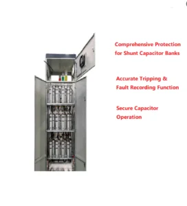
- In power system and substation automation, capacitor bank protection relay is a widely applied type of relay protection product, and the ASC-441H digital capacitor protection and control unit is perfectly suited for medium- and low-voltage shunt compensation capacitor banks, acting as bay-level equipment for capacitor units.
Protection Features of Capacitor Protection Relay
| Protection Function | ANSI Code |
|---|---|
| Three-stage definite time overcurrent protection | 50 / 51 |
| Zero-sequence overcurrent protection | 50N / 51N |
| Zero-sequence overvoltage protection | 59N |
| Overvoltage protection (no-current interlock optional) | 59 |
| Undervoltage protection (current presence interlock optional) | 27 |
| Control circuit disconnection | 74 |
| CT disconnection / Current transformer breakage | 60 |
| Bus PT disconnection / Bus VT failure | 60 |
Communication Mode
- Optional: RS-485, CAN bus, Ethernet,IEC 61850 , IEC 60870-5-103
Main Functional Specifications
| Item | Specification |
|---|---|
| Protection response time | Average error ≤ 35 ms (including output relay response time) |
| Precision operating range | 0.08 In ~ 20 In |
| Current setting error | ≤ ±2.5% (Current > 1.00 A) |
| Voltage setting error | ≤ ±3% |
| Measurement accuracy (I / U) | Class 0.2 |
| Measurement accuracy (P / Q) | Class 0.5 |
| Remote signal resolution | ≤ 2 ms |
Event Logging, Fault Recording
| Item | Description |
|---|---|
| Event Recording | Logs protection trips & device faults, including trip type, time and operating parameters |
| Fault Recording Data | Protection action time, action type, and RMS values before & after trigger |
| Fault Recording Length | 2 cycles before fault, 4 cycles after fault |
| Power-off Data Retention | 48 sets of SOE data, 16 sets of fault reports |
capacitor bank protection relay application
- The capacitor protection and relay unit provides real-time monitoring of voltage, current, temperature, and unbalance. By guarding against overvoltage, overcurrent, and internal faults, it ensures the reliability of reactive power compensation equipment within the power system.
Protective Relay Setting Document
| No. | Display Name | Range | Step | Remarks |
|---|---|---|---|---|
| 1 | Stage 1 Protection Setting | |||
| 1.1 | Stage 1 Protection Enable/Disable | 1/0 | — | Stage 1 protection: Enable(1) / Disable(0) |
| 1.2 | Stage 1 Time Delay | 0.00~120.00s | 0.01s | |
| 1.3 | Stage 1 Setting Value | 0.40~99.99A
0.10~20.00A |
0.01A | In=5A
In=1A |
| 2 | Stage 2 Protection Setting | |||
| 2.1 | Stage 2 Protection Enable/Disable | 1/0 | — | Stage 2 protection: Enable(1) / Disable(0) |
| 2.2 | Stage 2 Time Delay | 0.00~120.00s | 0.01s | |
| 2.3 | Stage 2 Setting Value | 0.40~99.99A
0.10~20.00A |
0.01A | In=5A
In=1A |
| 3 | Stage 3 Protection Setting | |||
| 3.1 | Stage 3 Protection Enable/Disable | 1/0 | — | Stage 3 protection: Enable(1) / Disable(0) |
| 3.2 | Stage 3 Time Delay | 0.00~120.00s | 0.01s | |
| 3.3 | Stage 3 Setting Value | 0.40~99.99A
0.10~20.00A |
0.01A | In=5A
In=1A |
| 4 | Overvoltage Protection Setting | |||
| 4.1 | Overvoltage Protection Enable/Disable | 1/0 | — | Overvoltage protection: Enable(1) / Disable(0) |
| 4.2 | Overvoltage Time Delay | 0.00~120.00s | 0.01s | |
| 4.3 | Overvoltage Setting Value | 5.00~120.00V | 0.01V | |
| 5 | Undervoltage Protection Setting | |||
| 5.1 | Undervoltage Protection Enable/Disable | 1/0 | — | Undervoltage protection: Enable(1) / Disable(0) |
| 5.2 | Undervoltage Time Delay | 0.00~120.00s | 0.01s | |
| 5.3 | Undervoltage Setting Value | 5.00~100.00V | 0.01V | |
| 6 | Zero-sequence Overcurrent Setting | |||
| 6.1 | Zero-sequence Overcurrent Protection | 1/0 | — | Zero-sequence overcurrent protection: Enable(1) / Disable(0) |
| 6.2 | Zero Current Time Delay | 0.00~120.00s | 0.01s | |
| 6.3 | Zero Current Setting Value | 0.02~5.00A
0.50~99.00A |
0.01A | Small current grounding system
380V three-phase four-wire single-phase grounding system |
| 7 | Zero-sequence Overvoltage Setting | |||
| 7.1 | Zero-sequence Overvoltage Protection | 1/0 | — | Zero-sequence overvoltage protection: Enable(1) / Disable(0) |
| 7.2 | Zero Voltage Time Delay | 0.00~120.00s | 0.01s | |
| 7.3 | Zero Voltage Setting Value | 0.00~120.00V | 0.01V | |
| 8 | Phase-to-Ground Undervoltage Setting | |||
| 8.1 | Phase-to-Ground Undervoltage Enable/Disable | 1/0 | — | Phase-to-ground undervoltage protection: Enable(1) / Disable(0) |
| 8.2 | Undervoltage Time Delay | 0.00~120.00s | 0.01s | |
| 8.3 | Undervoltage Setting Value | 5.00~70.00V | 0.01V | |
| 9 | Phase-to-Ground Overvoltage Setting | |||
| 9.1 | Phase-to-Ground Overvoltage Enable/Disable | 1/0 | — | Phase-to-ground overvoltage protection: Enable(1) / Disable(0) |
| 9.2 | Overvoltage Time Delay | 0.00~120.00s | 0.01s | |
| 9.3 | Overvoltage Setting Value | 5.00~70.00V | 0.01V | |
| 10 | CT Break Setting | |||
| 10.1 | CT Break | 1/0 | — | CT break alarm: Enable(1) / Disable(0) |
| 10.2 | CT Break Setting Value | 0.10~5.00A | 0.01A | |
| 10.3 | CT Break Time Delay | 1.00~999.99s | 0.01s | |
| 10.4 | Load Current Setting Value | 0.05~5.00A | 0.01A | |
| 11 | General Setting | |||
| 11.1 | Bus PT Break | 1/0 | — | Bus PT break detection: Enable(1) / Disable(0) |
| 11.2 | Control Circuit Break | 1/0 | — | Control circuit break: Enable(1) / Disable(0) |
| 11.3 | Current Blocking Over/Undervoltage | 1/0 | — | Current blocking over & undervoltage protection: Enable(1) / Disable(0) |
| 11.4 | Current Rated 1A | 1/0 | — | Enable(1)=1A / Disable(0)=5A |
| 11.5 | B17 as Maintenance Plate | 1/0 | — | B17 maintenance plate: Enable(1) / Disable(0) |
| 11.6 | Integral Energy Calculation | 1/0 | — | Calculate integral energy(1) / Not calculate(0) |
| 11.7 | Harmonic Component Calculation | 1/0 | — | Calculate harmonic component(1) / Not calculate(0) |
| 11.8 | Current Blocking Value | 0.00~99.99A | 0.01A | Current blocking setting value |
| 11.9 | Sudden Change Startup | 0.00~99.99A | 0.01A |
Outline and Installation Dimensions of Capacitor Bank Protection Relay


FAQ
Q:What is the difference between a feeder protection relay and a capacitor protection relay?
A:Feeder protection relays are mainly applied to line feeders with three-stage current protection as their core relay protection function. As professional capacitor bank unbalance protection relay devices, capacitor bank protection relays adopt complete relay protection configurations; besides three-stage current protection, they also feature overvoltage protection, undervoltage protection and unbalance current protection for capacitor banks.
Q: What protection functions are integrated?
A: Overvoltage(59), undervoltage(27), phase overcurrent(51), unbalance protection(46), zero-sequence overvoltage(59N) for capacitor bank fault protection.
Q: What is the purpose of unbalance protection?
A: Detect single capacitor breakdown inside the group, cut off faulty capacitor bank to prevent cascading damage.
Q: Communication options?
A: Optional RS-485, Ethernet, IEC 60870-5-103 for remote setting and fault data upload.
Q: Typical application?
A: Used in high/low voltage reactive power compensation cabinet in substation and industrial power distribution system.
Q: Can protection delay be adjusted?
A: Yes, independent adjustable delay for each protection item to avoid malfunction caused by switching transient surge.


xiao zhang –
This Capacitor Bank Protection Relay (ANSI59/46/51/59N) integrates overvoltage, undervoltage, unbalance and overcurrent protection. Reliable protection logic, flexible parameter setting and multiple communication choices fit reactive power compensation cabinets worldwide.
Jack –
Good compatibility, stable communication — a solid product.