Earth fault ranks among the most frequent faults occurring in power systems.
Failure to detect earth faults in a timely manner may lead to severe consequences including equipment damage, burnt cables, transformer malfunctions, arc flash incidents and unexpected power outages.
For this reason, earth fault relays serve as essential protective devices widely deployed in utility substations, industrial plants, solar power stations, wind farms and commercial buildings.
What is earth fault relay
An Earth fault monitoring relay monitors abnormal leakage current between phase conductors and earth. It triggers an alarm or trip signal once earth current exceeds preset threshold value.
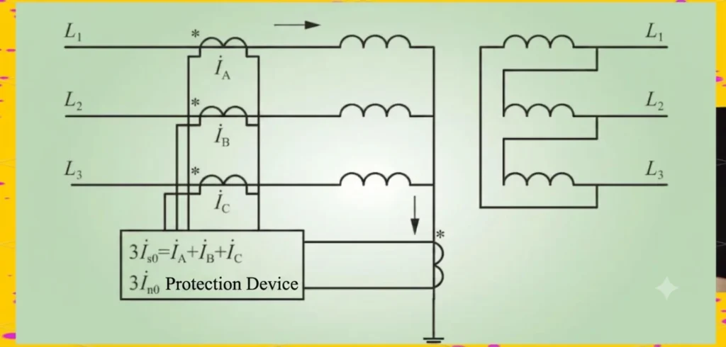
Earth fault relay circuit diagram
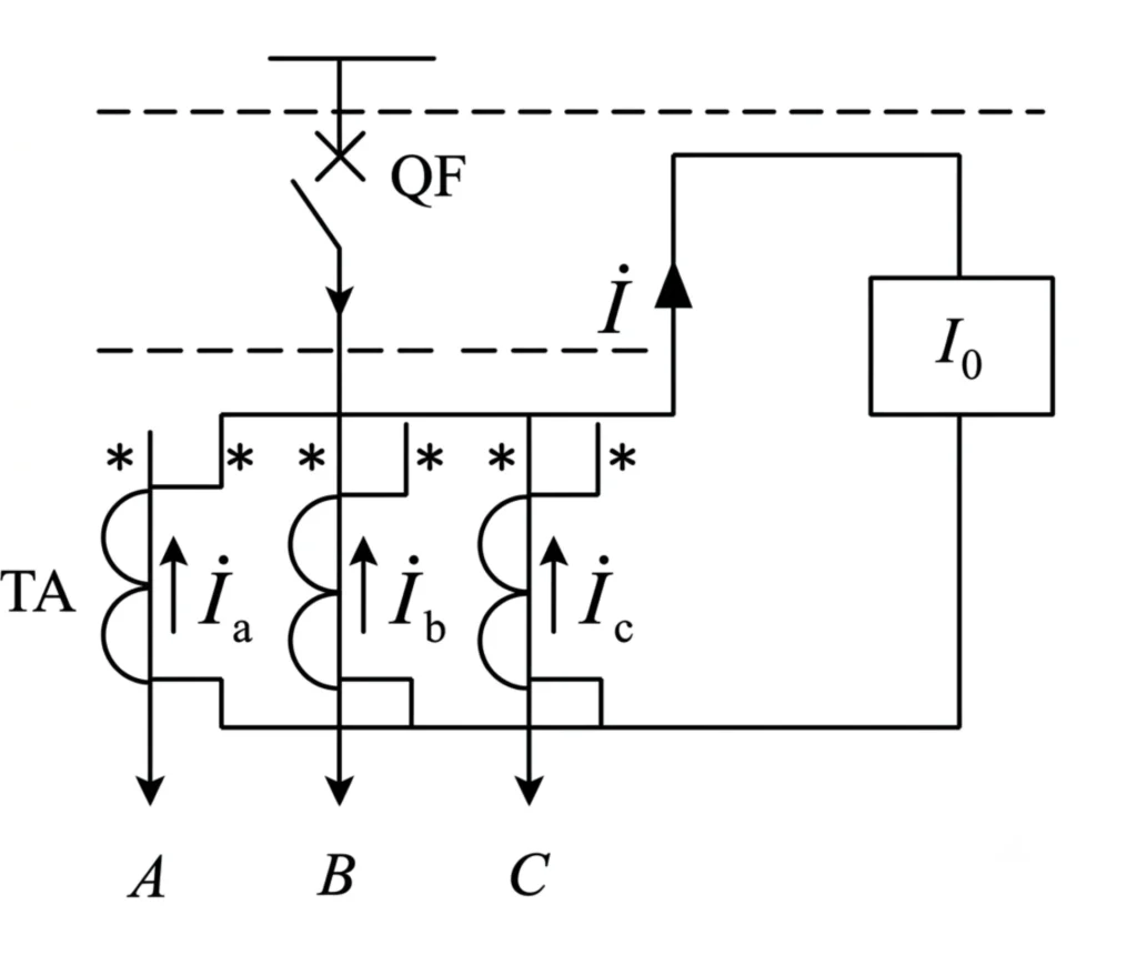
How Earth Fault Relay Works
Earth fault protection relay monitors residual current via current transformers. Under normal operating conditions, the vector sum of three-phase currents equals zero, with no residual current flowing through the relay.
Working Principle: Residual Current Method
Normal condition:
Ia+Ib+Ic=0
The vector sum of three-phase currents is zero.
Earth fault occurs:
Ia+Ib+Ic≠0→ Residual current generated.
Once Residual Current > Setting Value, the relay operates.
Earth fault relay connection
How is the directional earth fault relay energized
The directional earth fault relay is energized from two input signals measured by CT and VT:
- Residual current (from zero-sequence CT) – operating current input
- Residual voltage (from zero-sequence VT) – polarizing voltage input
The relay judges fault direction via phase angle between residual current and residual voltage; when fault direction matches the protection setting, the relay gets energized and trips.
Why Is Earth Fault Protection Important?
Undetected earth faults can result in costly and dangerous operational issues:
- Permanent transformer damage
- Cable insulation breakdown
- Destructive arc flash accidents
- Potential fire risks
- Unplanned production shutdown
Real Case Study
A minor hidden earth fault inside an industrial facility went unnoticed over several weeks.
The persistent fault degraded cable insulation until complete failure, incurring repair expenses over USD 50,000.
Difference between earth fault relay and overcurrent relay
| Comparison Point | Overcurrent Relay (50/51) | Earth Fault Relay (50N/51N) |
|---|---|---|
| Monitored Current | 3-phase line/phase current | Residual / zero-sequence earth current |
| Protected Faults | Phase-phase short circuit, overload, severe high-current earth faults | Phase-earth leakage, insulation breakdown, all ground faults (no phase-phase protection) |
| Sensitivity | Low (high pickup setting) | High (detects small earth leakage) |
| Typical Setting | 125%–200% of full load current | 5%–30% of full load current |
| CT Connection | Individual CT per phase | Residual summation CT / Zero-sequence CT (ZCT) |
| Core Function | Protect equipment from overload & phase short faults | Protect system & personnel from earth/ground leakage faults |
Common Causes of Earth Faults
Cable Insulation Deterioration
Undetected residual leakage gradually triggers cable earth fault and accelerates insulation failure, eventually leading to costly equipment damage and unexpected plant outages.
Moisture and Water Ingress
Moisture and water ingress frequently occurs at solar farms, outdoor substations and wind power plants, triggering hidden leakage current that evolves into cable earth fault and eventually causes severe insulation failure.
Aging Electrical Equipment
Aging Electrical Equipment including Switchgear, Transformers and Motors, alongside moisture and water ingress at solar farms, outdoor substations and wind power plants, produces invisible leakage current, gradually leading to cable earth fault and permanent insulation failure.
Mechanical Damage
Mechanical Damage from excavation, rodent damage and vibration, aging electrical equipment including switchgear, transformers and motors, as well as moisture and water ingress at solar farms, outdoor substations and wind power plants, all create hidden leakage current, progressing into cable earth fault and irreversible insulation failure.
Incorrect Wiring
Fault Description: Improper cable connection, reversed wiring or neutral-earth misconnection causes false earth faults and nuisance tripping of earth protection. Inspect primary and secondary wiring and correct wrong connections.
Types of Earth Fault Relays
Overcurrent Earth Fault Relay (50N/51N)
It is the most widely adopted earth fault protection type.
Application:
- Distribution feeders
- Industrial power systems
Brief function introduction:
ANSI 50N provides instantaneous earth fault tripping when zero-sequence current exceeds setting value.
ANSI 51N features inverse or definite time delayed tripping for earth overcurrent protection, serving as backup protection for feeders.
Sensitive Earth Fault Relay (SEF)
Sensitive Earth Fault (SEF) relay is designed to detect low-magnitude earth fault currents that cannot be captured by standard 50N/51N overcurrent earth protection.
Applications:
- Medium voltage (MV) networks
- Transformer protection
It adopts high-sensitivity zero-sequence current acquisition, suitable for neutral earthing via arc suppression coil or high-resistance grounded systems, preventing minor leakage from deteriorating into equipment insulation breakdown.
Directional Earth Fault Relay (ANSI 67N)
This directional earth fault protection (67N) judges fault current direction to avoid unwanted nuisance tripping.
Applications:
- Ring main distribution networks
- Dual-source power supply systems
- Renewable energy power plants
ANSI 67N directional zero-sequence earth fault protection is widely deployed on multi-source tie lines and grid-connected feeders of distributed PV systems. It eliminates nuisance tripping on healthy branches during faults in ring or dual-supply networks.
Earth Fault Relay Applications
Utility Substations
Various ANSI earth & overcurrent protection relays (50N/51N, SEF, 67N) are configured to safeguard feeders, transformers and busbars inside utility substations against earth faults and overcurrent damages.
Solar Power Plants
Dedicated earth fault protection is configured for solar power plants to resolve typical site faults including PV cable insulation breakdown and abnormal inverter grounding, effectively avoiding false tripping and equipment burnout induced by incorrect wiring.
Wind Farms
Protection covers wind farm collection circuits and transformer feeders. High-sensitive SEF & directional 67N earth fault relays are commonly equipped to detect subtle cable insulation faults and avoid nuisance tripping on collector feeders.
Industrial Facilities
Protection scope includes motors, MCC and switchgear. 50N/51N earth overcurrent protection plus sensitive SEF protection are widely used to guard against winding leakage and cable earthing faults inside industrial distribution systems.
How to Select an Earth Fault Relay
System Voltage
Earth fault relay type is determined according to system voltage:
LV System: Adopt standard 50N/51N overcurrent earth fault relay for general distribution, SEF for equipment with high insulation requirement.
MV System: Configure SEF sensitive earth fault relay plus 67N directional earth fault relay for ring networks & renewable collection lines.
HV System: Apply dedicated directional earth protection matched with substation primary equipment.
Grounding Method
Four Main Neutral Earthing Configurations
Solid Grounded System
Standard ANSI 50N/51N overcurrent earth fault relays are the primary choice. High earth-fault current ensures stable and dependable fault detection.
Resistance Grounded System
A combination of 51N plus SEF sensitive earth fault protection is adopted to detect both heavy short-circuit earth faults and minor leakage faults.
Petersen Coil (Arc Suppression Coil) Grounded System
SEF high-sensitivity earth fault relay is essential, as residual fault current remains extremely low under ground fault conditions.
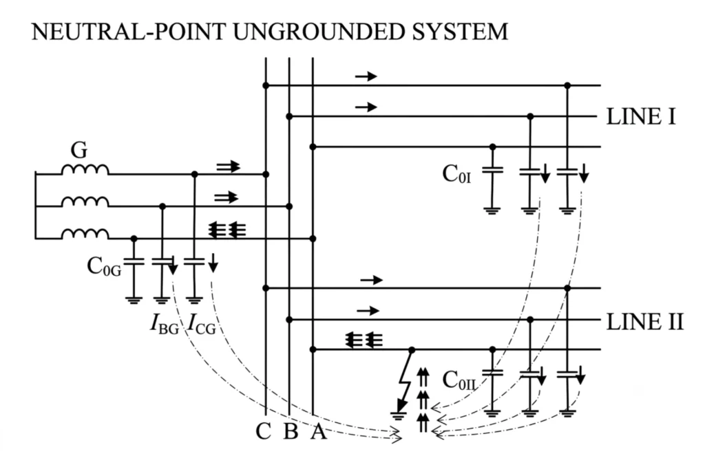
Ungrounded System
SEF paired with 67N directional earth fault relay is recommended to identify faint insulation degradation and subtle earth faults.
Summary
The selection of earth fault relays is determined by the system’s neutral grounding scheme; the application scope of SEF and 67N varies greatly across different earthing types.
Communication Requirements
Modern projects support multiple mainstream communication protocols for earth fault relays:
- Modbus RTU
- Modbus TCP
- IEC 61850
- IEC 60870-5-104 (IEC 104)
- DNP3
The earth fault protection relays are equipped with versatile communication interfaces to meet modern automation demands. Data including fault records, measured values, protection setting parameters and relay status can be uploaded to SCADA or central control system via above protocols.
Integration with SCADA
Remote monitoring capability has become a key concern for most customers. Protection relays upload real-time operating data, fault alerts and protection parameter values to SCADA systems via standard communication protocols, enabling centralized remote supervision and fault diagnosis from control rooms.
Earth Fault Relay Setting Guide
Pickup Current Setting
The pickup current is typically set between 10% and 30% of the maximum system earth fault current. This setting prevents nuisance tripping from unbalanced load currents and natural cable leakage while guaranteeing reliable operation during actual earth faults.
Time Delay Setting
Time delay is configured to balance protection security and selectivity. Proper graded time coordination avoids unwanted nuisance tripping (security) and ensures only the faulty feeder trips under fault conditions (selectivity).
Coordination with Upstream Protection
Time grading coordination with upstream protection is implemented to eliminate nuisance tripping. Fault isolation is limited to the faulty section only without unnecessary tripping of upstream healthy feeders.
Common Earth Fault Relay Problems and Solutions
Why Does My Earth Fault Relay Keep Tripping?
Common Root Causes
Common Root Causes
- Moisture penetration inside switchgear or field equipment
- Insulation leakage of buried/run cables
- Reversed CT connection polarity
- Improperly configured relay pickup & time delay settings
Troubleshooting Solution
Conduct systematic item-by-item inspection to pinpoint the fault source.
Why Doesn’t the Relay Detect an Earth Fault?
Main Causes
- Improper CT wiring mistakes
- Excessively high pickup current setting
- Extremely low actual earth fault current
Suggested Remedy
Recheck CT wiring, readjust pickup value and verify on-site fault current level accordingly.
Why Is the Relay Generating False Alarms?
Root Causes
- Harmonic distortion in system current
- Electromagnetic interference & electrical noise
- Inadequate or unreliable site grounding
Recommended Fixes
Filter system harmonics, shield signal cables and upgrade the equipment grounding layout.
Why Does the Relay Trip During Motor Starting?
Root Cause
Unfavourable influence from high inrush current during motor startup.
Solutions
- Extend protection time delay
- Modify the relay pickup setting value
Modern Features of Digital Earth Fault Relays
| Feature Name | Detailed Function Description |
|---|---|
| Self-Diagnostics | Real-time device health monitoring |
| Event Recording | Full event log for fault and abnormal operation history |
| Fault Waveform Capture | High-resolution oscillography function to capture fault waveforms |
| Multiple Protection Functions | Built-in ANSI standard protection elements:• 50/51: Phase overcurrent protection• 50N/51N: Neutral earth fault overcurrent protection• 67N: Directional neutral overcurrent protection• 49: Thermal overload protection for winding• 46: Negative sequence overcurrent protection |
| IEC 61850 Communication | Fully compliant for digital substation applications |
| Cybersecurity Features | Meets international cybersecurity standards:• IEC 62351• NERC CIP |
Earth Fault Relay vs Residual Current Device (RCD)
| Feature | Earth Fault Relay | RCD |
|---|---|---|
| Industrial Use | Yes | Limited |
| Adjustable Setting | Yes | No |
| SCADA Integration | Yes | No |
| IEC61850 Support | Yes | No |
Future Trends in Earth Fault Protection
| Future Trends | Description |
|---|---|
| Smart Substations | Full-scale adoption of IEC 61850 standard |
| Renewable Energy Protection | Rapid expansion of solar PV and wind power installations |
| AI-Based Fault Detection | Enable predictive maintenance for power equipment |
| Remote Monitoring | Cloud-based monitoring and centralized management |
Conclusion
Proper selection of an Earth Fault Relay protects equipment, improves overall system reliability, minimizes downtime, and fulfills the requirements of modern smart grid and renewable energy projects.
For projects requiring long-term stable operation and remote monitoring, digital protective relays equipped with Multi-Protocol Communication, IEC 61850 Compatibility, Fault Recording and Advanced Earth Fault Detection are highly recommended.
FAQ
How to check earth fault relay?
Inspect wiring and CT connection, verify settings, perform secondary injection test and check recording & communication to complete earth fault relay inspection.
How to connect earth fault relay?
Connect CT residual circuit to relay input terminals, confirm correct polarity then wire auxiliary trip and communication circuits.
How to set earth fault relay?
Set pickup current and time delay per system parameters for selective coordination.
How to test directional earth fault relay?
Inject phase-shifted test current to verify operating direction and pickup threshold of directional earth fault relay.
Where earth fault relay is employed?
Installed on distribution panels, transformer feeders, motor circuits and renewable energy collection feeders.
Why earth fault relay trip?
It trips due to actual earth fault, improper setting, wrong CT polarity, cable leakage or motor starting inrush current.
Related Products
Low Current Earth Fault Line Selector