With continuous growth of global installed photovoltaic capacity, solar power substations have become an indispensable component of new energy power grids.
Nevertheless, numerous photovoltaic power generation systems and solar plants commonly encounter operational troubles including transformer failures, unnecessary relay nuisance trips, grid connection malfunctions, ground faults, reverse power flow and arc flash accidents, making the design of dependable electrical protection systems a top priority for both EPC contractors and solar plant owners.
This article covers:
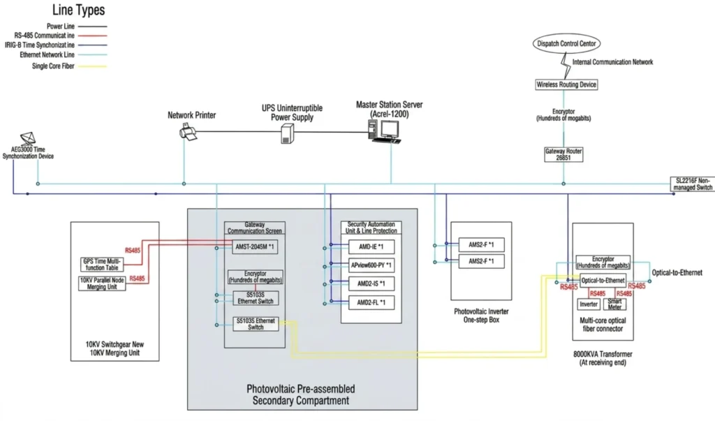
- Solar substation protection architecture
- Electrical Protection Relay Applications
- Common protection challenges
- Relay setting recommendations
- Best practices for improving reliability
What Is Electrical Protection in a Solar Power Substation?
Electrical Protection refers to a full relay-based protection system that detects faults and initiates tripping for transformers, switchgears, collector feeders and inverter grid-tie circuits in solar substations.
The system prevents equipment damage caused by short circuits, ground faults and reverse power flow to guarantee safe operation of power plants and utility grids.
Protection Targets
Step-up Transformer
| Equipment Name | Brief Function |
|---|---|
| Transformer Differential Protection Relay (87T) | Main protection to instantly clear internal phase and earth faults of transformer; percentage restraint prevents maloperation caused by inrush current. |
| HV Side Backup Protection Relay (51/51N/27/59) | High-voltage backup protection with voltage-restrained overcurrent & zero-sequence protection, trips with graded delay if main protection fails or feeder faults occur. |
| LV Side Backup Protection Relay (51/51N) | Low-voltage backup for LV busbar and inverter feeders, cuts off short-circuit and earth faults with staged time delay. |
| Non-electrical Protection Device | Processes Buchholz gas, oil temperature, oil level and pressure signals; heavy gas triggers tripping while light gas and over-temperature generate alarms. |
| Transformer Measurement & Control Device | Collects electrical parameters and breaker status, completes four remote functions and transmits data to control system via communication. |
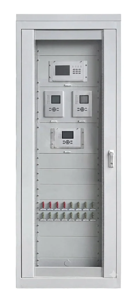
Normally, one set of transformer protection panel is equipped for each step-up transformer.
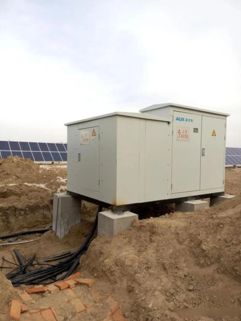
Inverter Transformer
Inverter transformers are scattered throughout PV sites. Box-type measurement & control units provide protection and data collection, gather inverter data and upload to SCADA. These units monitor electrical values and breaker status, trigger alarms or trips during faults, and realize centralized management via standard communication protocols.
Medium Voltage Feeders
Protection devices are mounted on switchgears to trip and isolate faulty feeders upon faults. Classified as feeder relays, they come with standard directional overcurrent protection and are pre-installed inside switch cabinets.
Direction discrimination prevents false tripping resulting from reverse power flow typical of PV stations. Equipped with earth fault and multi-stage overcurrent protection, their setting values are configured hierarchically per grid parameters. All operational and fault data is uploaded centrally to the SCADA system.
Busbars
As the main protection for substation busbars, bus differential protection instantly clears phase and earth faults on busbars to avoid massive blackout of the entire collection system.
Projects with voltage of 33kV and above are generally required to deploy bus differential protection devices, which are commonly assembled into dedicated protection panels on site.
Transmission Lines
It transmits total power from the step-up substation to the external grid and is equipped with distance protection or optical fiber differential protection. Note that optical fiber differential relays are supplied as complete sets; identical model equipment must be installed at both the substation and opposite terminal for proper operation, and such devices are usually arranged in assembled protection panels.
Capacitor Banks
Capacitor banks are installed inside the step-up substation to compensate reactive power, regulate voltage, improve power factor and stabilize voltage fluctuations induced by variable PV generation. Corresponding capacitor protection relays are generally mounted on capacitor switchgears.
Auxiliary Power Systems
Station service transformers supply domestic power for the power station, covering lighting, air conditioning and other loads to ensure normal operation of auxiliary facilities.
In field application, a dedicated transformer protection device is required when the transformer is fitted with vacuum circuit breakers, whereas no such protection is needed for load-switch configurations.
Regardless of the switch type, all operational data of the station service transformer shall be collected via the common measurement & control panel and transmitted to the SCADA system.
Why Electrical Protection Is Critical for Solar Substations
What Happens Without Proper Protection?
| Problem | Potential Loss |
|---|---|
| Transformer damage | $50,000–$500,000 |
| Inverter failure | Production loss |
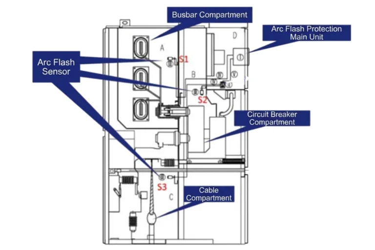
| Arc flash accidents | Personnel injury |
| Long outage times | Revenue loss |
| Grid code violations | Utility penalties |
Effective relay solutions improve solar plant reliability, strengthen solar farm protection and guarantee full grid compliance; therefore, operating a solar plant without protective devices is prohibited by power industry regulations.
Main Protection Relays Used in Solar Power Substations
Effective relay solutions improve solar plant reliability, strengthen solar farm protection and guarantee full grid compliance; therefore, operating a solar plant without protective devices is prohibited by power industry regulations. Main Protection Relays Used in Solar Power Substations
| Protection Item | Function & Protected Object |
| Transformer Differential Relay (87T) | Applied to main transformers and station service transformers. Serves as the main transformer protection to quickly isolate internal short-circuit faults. |
| Overcurrent & Earth Fault Relay (51/51N) | Used for main transformers, outgoing lines, capacitor banks and station service transformers to prevent phase-to-phase short circuits and ground faults. |
| Over/Under Voltage Relay (59/27) | Configured for busbars, capacitor banks and auxiliary power systems to monitor and suppress abnormal voltage fluctuations. |
| Negative Sequence Protection (46) | Applied to main transformers to cope with system three-phase unbalance and non-full-phase operation faults, ensuring equipment safety. |
| Distance Protection (21) | Used for grid-connected outgoing lines to accurately identify fault sections and realize rapid fault isolation. |
| Fiber Optic Line Differential (87L) | Serves as the main protection for grid-connected outgoing lines with fast operation speed and high reliability. |
| Directional Overcurrent (67) | Applied to medium-voltage collection lines and grid-connected lines to judge fault power direction and avoid false tripping. |
| Capacitor Unbalance Protection (60C) | Designed for capacitor banks to monitor damage of single capacitors and three-phase capacity unbalance faults. |
| Reverse Power Protection (32) | Installed for main transformers to prevent reverse power transmission from the solar power station to the grid and meet grid connection standards. |
| Busbar Differential Protection (87B) | Applied to high-voltage and medium-voltage busbars to quickly clear busbar short-circuit faults and ensure stable power supply of the whole station. |
| Auxiliary Power Protection | Used for station service transformers and auxiliary power loads to ensure stable power supply for station lighting, air conditioning and control equipment. |
| Islanding Protection | Applied to the whole station grid-connected system. It enables rapid off-grid operation during sudden grid power failure to prevent islanding operation, guarantee grid operation and maintenance safety and meet grid compliance requirements. |
Common Electrical Protection Problems in Solar Power Substations
Problem #1: Nuisance Tripping During Cloud Transients
Weather-induced power generation fluctuations alongside sensitive relay settings and poor protection coordination easily lead to nuisance tripping relay and relay false trip; targeted solutions include adjusting pickup values and deploying adaptive protection to resolve such undesired tripping issues.
Problem #2: Relay Maloperation Due to Harmonics
Harmonics generated by solar inverters cause relay harmonic issues including false differential trips and incorrect measurements, which can be mitigated via harmonic restraint and harmonic filtering equipped in inverter harmonics protection.
Problem #3: Transformer Inrush Current Causing False Trips
Transformer energization generates magnetizing inrush current, which may trigger differential relay false trip; the problems can be solved by adopting second harmonic blocking and inrush restraint algorithms for transformer inrush current relay.
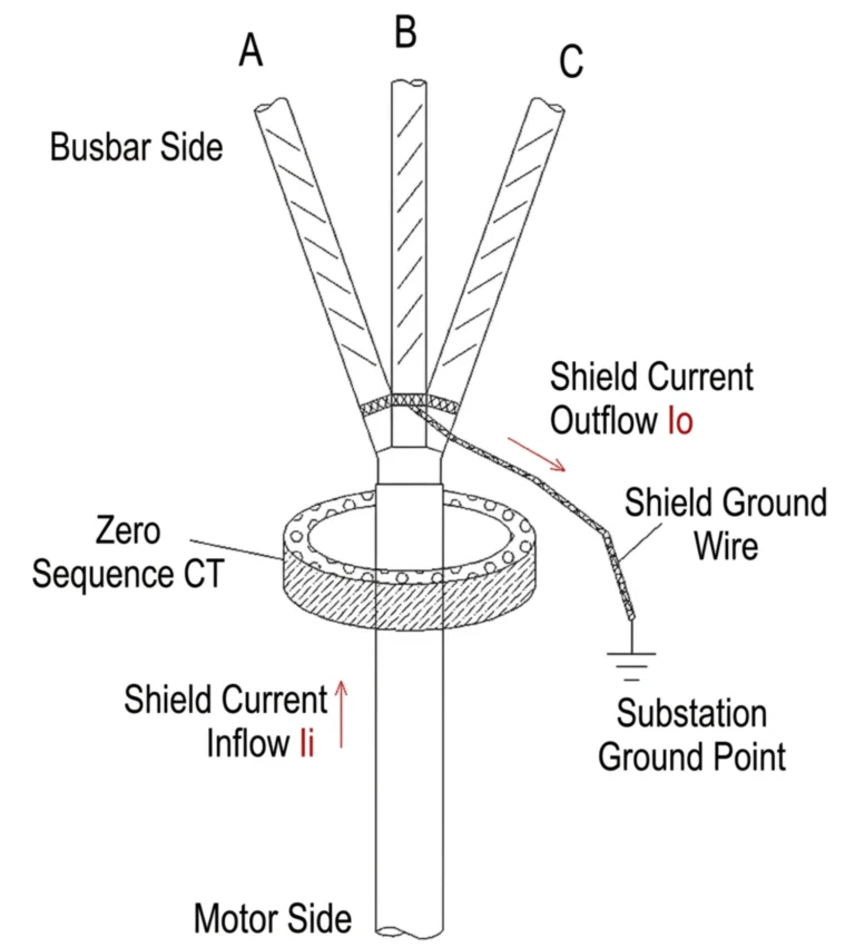
Problem #4: Ground Fault Detection Challenges
High-resistance grounded system easily brings hidden earth fault risks, which can be addressed by deploying sensitive earth fault relays and directional earth fault protection.
How to Select Protection Relays for a Solar Substation
Define Voltage Level
Electrical Protection varies by voltage class per global grid standards; categorized into LV, MV, HV and EHV with typical ratings of 11kV, 22kV, 33kV, 66kV, 110kV, it adopts fuller relay configurations for larger-capacity PV stations at higher voltage grades.
Identify Protection Requirements
Electrical Protection defines required relay functions according to system voltage, PV capacity and operating mode to fulfill grid codes, with tailored schemes coping with overcurrent, earth faults, reverse power, inrush current and harmonic-triggered nuisance tripping.
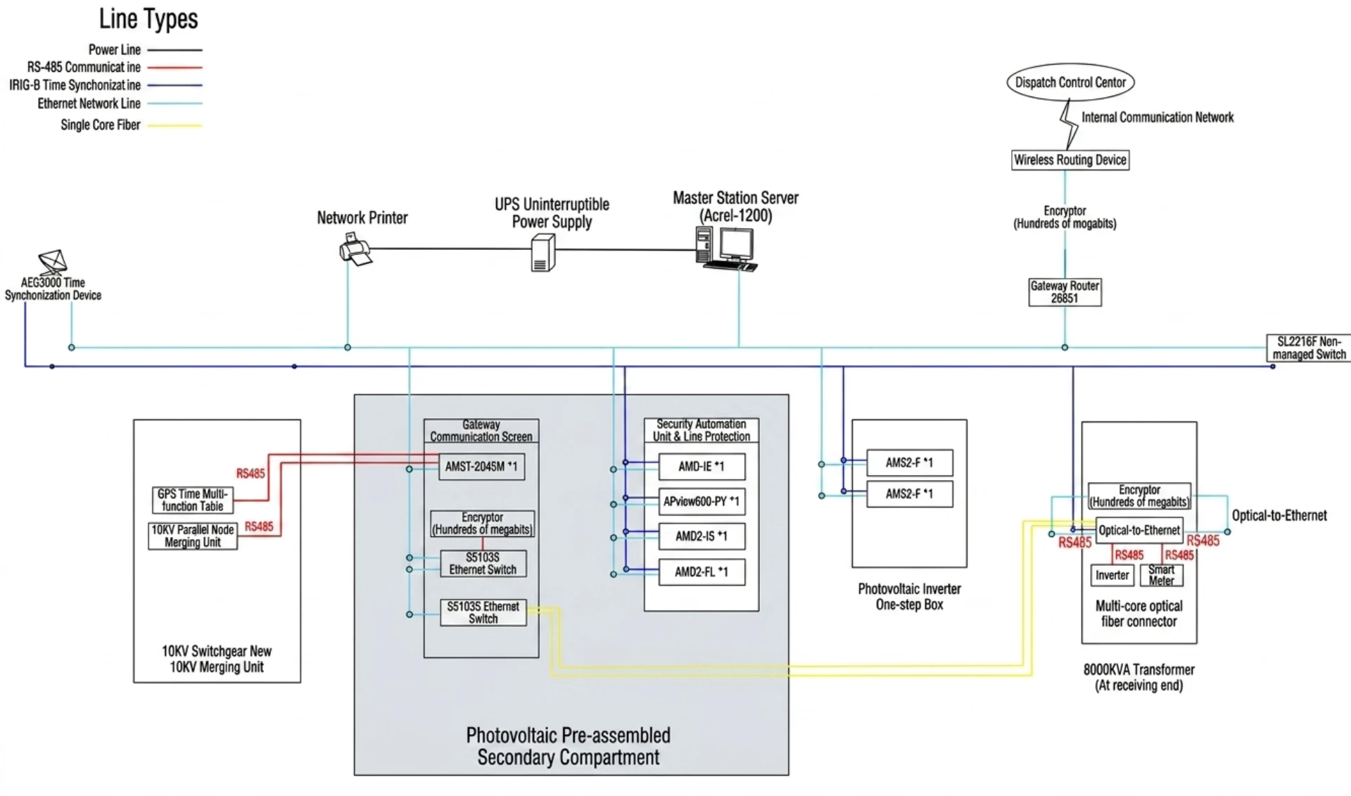
Verify Communication Protocols
Electrical Protection also covers the verification of communication protocols, which checks the compatibility of data transmission standards including IEC60870-5-103, IEC61850 and Modbus between protection relays, RTU and SCADA systems, ensuring stable remote data transmission and reliable remote control for solar substation protection operation.
Ensure Grid Code Compliance
Our Electrical Protection relay products ensure Grid Code Compliance and fully comply with IEEE standards, IEC standards and local utility technical requirements.
Best Practices for Solar Substation Protection Design
Use Numerical Protection Relays
Use Numerical Protection Relays, which feature prominent advantages of higher measurement accuracy, built-in self-diagnostics and accessible remote monitoring functions.
Perform Proper Relay Coordination Studies
Perform Proper Relay Coordination Studies to avoid unnecessary outages and protection overlap.
Conduct Routine Testing
Conduct Routine Testing; recommended items include annual relay testing, secondary injection tests and functional verification.
Future Trends in Solar Power Substation Protection
Hot industry topics with rapidly rising overseas search volume in recent two years cover Digital Protection Systems, AI-Based Fault Detection, Adaptive Relay Settings, Wide Area Protection Systems and IEC 61850 Process Bus.
Nevertheless, it should be noted that the evolution of relay protection does not equate to unlimited pursuit of higher intelligence. All intelligent functions must be developed on the premise of reliability, stability and operational safety.
Frequently Asked Questions (FAQ)
What protection relays are required in a solar power substation?
Standard solar substations need grid-code compliant relays: overcurrent, earth fault, directional power, transformer differential, over/undervoltage, over/underfrequency and breaker failure protection. Large PV stations additionally require high-sensitivity earth fault and adaptive grid-tie protection per grid interconnection rules.
How do I prevent nuisance tripping in solar farms?
Prevent nuisance tripping via relay coordination calculation, optimized adaptive setting, harmonic-proof numerical relays, transient delay setup and periodic secondary injection test. Directional protection also avoids false trips from reverse power and fluctuating PV output.
What is the best relay for transformer protection?
Multifunction numerical transformer protection relay is the optimal choice, integrating differential main protection, backup overcurrent, overexcitation and thermal monitoring, compliant with IEC & IEEE standards.
Why does my differential relay trip during energization?
Differential trips on transformer energization mainly result from magnetizing inrush current, which resembles fault current. Enable inrush restraint logic, set proper time delay or adopt advanced algorithm-based differential relays to distinguish inrush from real faults.
How often should solar substation relays be tested?
Complete functional tests including secondary injection shall be implemented yearly for all protection relays. Large critical grid-tied solar substations require quarterly routine inspection and biennial full calibration to avoid hidden faults.
Is IEC 61850 necessary for solar substations?
IEC 61850 is unnecessary for small low-voltage solar substations but essential for medium/high-voltage large PV plants. It enables device interoperability, lower wiring cost, remote diagnosis and intelligent substation management.
How can I improve protection coordination in a PV plant?
Optimize PV plant protection coordination via coordination study, graded TCC curves, adaptive settings matching variable PV output, directional protection to block reverse power flow, and unified protection logic per grid operation conditions.
Conclusion
A well-designed protection system for solar photovoltaic power generation system and its supporting solar substation prevents equipment damage, boosts plant availability, cuts downtime, meets grid codes and lifts long-term ROI.
For EPC contractors, project developers and O&M teams, properly selected and calibrated protection relays are critical to reliable PV operation.