


Description
Product Overview
- The AST-441H Digital Transformer Differential Protection|87T and Control Unit is suitable for transformer protection in substations with voltage levels of 110kV and below.
Product Functions (ANSI)
- Transformer High-Speed Differential Protection 87T-HI / 87HS
- Transformer Differential Protection Relay 87T
- CT Open-Circuit Detection and Excessive Differential Current Alarm
- Overcurrent-start fan
Communication Features
- Communication interfaces (optional): RS-485, CAN bus, Ethernet, IEC 60870-5-103.
- This transformer differential protection device uploads real-time data such as measurements, waveforms, fault and alarm messages, together with all protection parameters and configurations. It supports remote online setting modification and protection function switching.
- The device also accepts commands from the master station, including remote control, time synchronization, parameter adjustment and data access.
Event Logging, Fault Recording
- Event logs cover protection trips and device self-diagnostic faults. They record event type, occurrence time and operating parameters for protection trips, as well as fault type and time for self-test anomalies.
- Fault records include protection operation time, type and RMS values pre- and post-triggering.
- Each channel captures 2 pre-fault cycles and 4 post-fault cycles, with 192 sampling points per channel.
- The SOE stores up to 48 records and fault reports store up to 16 records after power loss.
General Technical Data
| No. | Parameter Category | Core Technical Specification |
|---|---|---|
| 1 | Power Supply & Rated Electrical Parameters | 1. Rated control voltage: AC/DC 220 V
2. Power supply ripple coefficient: ≤ 5% 3. Voltage tolerance: -20% to +15% 4. Rated AC current In: 1 A/5 A (specify when ordering) 5. Rated AC voltage: 100 V 6. Rated frequency: 50 Hz (customizable per project requirements) |
| 2 | Power Consumption | 1. DC power circuit: ≤ 25 VA (normal operation), ≤ 30 VA (device activated)
2. AC voltage circuit: ≤ 1 VA/phase (at 100 V rated voltage) 3. AC current circuit: ≤ 0.5 VA/phase (1 A In), ≤ 1 VA/phase (5 A In) |
| 3 | Output Contact Performance | 1. DC circuit: 50 W breaking capacity (voltage ≤ 250 V, current ≤ 0.5 A, time constant 5 ± 0.75 ms); allowable make current ≤ 5 A
2. AC circuit: 50 W breaking capacity (voltage ≤ 250 V); maximum allowable make current 5 A |
| 4 | Insulation Performance | Meets IEC standard requirements for insulation resistance, dielectric strength, and impulse voltage |
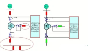
Working Principle of Transformer Differential Protection(
Setting Table of Transformer Differential Protection
| No. | Display Name | Range | Step | Remark |
|---|---|---|---|---|
| 1 | High-speed Differential Setting | |||
| 1.1 | High-speed Differential Protection | 1/0 | — | Enable(1) / Disable(0) |
| 1.2 | High-speed Differential Setting Value | 0.40~99.99A | 0.01A | |
| 2 | Differential Protection Setting | |||
| 2.1 | Differential Protection Enable | 1/0 | — | Enable(1) / Disable(0) |
| 2.2 | CT Broken Circuit Blocking Differential | 1/0 | — | CT break blocking function: Enable(1) / Disable(0) |
| 2.3 | Differential Current Setting | 0.50~99.99A | 0.01A | |
| 2.4 | Restraint Current Setting | 0.50~99.99A | 0.01A | |
| 2.5 | Differential Bias Current Setting | 0.50~99.99A | 0.01A | |
| 2.6 | CT Broken Circuit Threshold | 0.50~99.99A | 0.01A | |
| 2.7 | Harmonic Restraint Coefficient | 0.10~0.70 | 0.01 | Second harmonic restraint ratio |
| 2.8 | Slope / Ratio Restraint Coefficient | 0.30~0.70 | 0.01 | |
| 2.9 | Balance Coefficient | 0.100~1.999 | 0.001 | |
| 3 | Overcurrent Fan Control | |||
| 3.1 | Overcurrent Fan Start | 1/0 | — | Enable(1) / Disable(0) |
| 3.2 | Ventilation Time Delay | 0.00~999.99s | 0.01s | |
| 3.3 | Fan Start Current Setting | 0.5~99.99A | 0.01A | |
| 4 | General Setting | |||
| 4.1 | Motor Differential Mode Selection | 1/0 | — | |
| 4.2 | HV Side Y/△-11 Connection | 1/0 | — | |
| 4.3 | HV Side Y/△-01 Connection | 1/0 | — | |
| 4.4 | Secondary Wiring Mode | 1/0 | — | Delta/Y(1) / Y/Y(0) |
| 4.5 | Control Circuit Break Alarm | 1/0 | — | Alarm enable(1) / disable(0) |
| 4.6 | Current Angle Display | 1/0 | — | |
| 4.7 | Secondary Current Rated | 1/0 | — | 1A input(1) / 5A input(0) |
| 4.8 | Inter-tripping C6C7 | 1/0 | — | High-speed & differential trip C06C07(1) |
| 4.9 | Rated Secondary Current | 0.50~99.99A | 0.01A | HV side CT secondary rated current |
Outline and Installation Dimensions


FAQ
Q:What is the scope of protection provided by a transformer differential protection device?
A:Transformer differential protection primarily protects the internal components of the transformer. When a turn-to-turn short circuit or a phase-to-phase short circuit occurs inside the transformer, the corresponding protection function in the transformer differential protection device will trigger an alarm and trip the circuit.
Q:How to Select a Transformer Differential Protection Device?
A:When selecting a transformer differential protection device for differential protection of transformer and differential protection for transformer applications, three key points should be noted: first, consider the transformer’s capacity, as larger capacity requires more advanced device functions; second, identify whether the transformer is two-winding or three-winding, since the suitable protection device differs by transformer type; third, refer to relevant industry standards and verify compliance with international norms such as IEC and IEEE.


xiao zhang –
Transformer differential relay (87T) adopts percentage restraint algorithm, strong anti-CT-saturation capability and CT break lockout. Instant trip for internal winding faults, flexible parameter setting and multi-communication options for all types of distribution & power transformers.
Jack –
Backed by good technical support and documentation — overall a solid choice.